
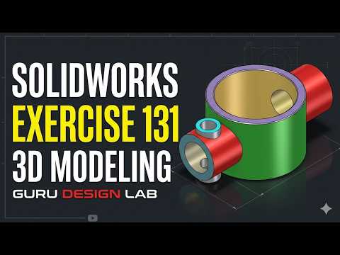
Transitioning from basic drafting to complex 3D modeling is a crucial milestone for any mechanical designer. In this step-by-step tutorial inspired by Guru Design Lab's SolidWorks Exercise 131, we break down the process of creating a complex Multi-Port Pipe Connector. Whether you are a beginner looking to build confidence or an experienced designer refining your workflow, understanding how to translate a SolidWorks 2D blueprint into a precise 3D component is essential for modern engineering.
Starting with SolidWorks 2D Blueprints
Every great 3D CAD model begins with an accurate, well-defined sketch. Before diving into advanced features like sweeps or lofts, you must thoroughly analyze the technical dimensions and geometric constraints. Working efficiently in SolidWorks 2D sketch mode allows you to establish proper relations, smart dimensions, and symmetry. For our multi-port pipe connector, establishing clear centerlines and primary diameter paths in the 2D layout ensures that all intersecting connection ports line up perfectly during subsequent extrusions and cuts.
Key Steps in Modeling the Multi-Port Connector
Building a multi-port connector requires a structured modeling approach to keep your feature tree clean and error-free. Here is a breakdown of the design workflow:
- Base Feature Creation: Start by sketching the primary profile on a main plane, then use a Revolved Boss/Base or Extruded Boss to form the central core body.
- Adding Secondary Branches: Create offset or angled reference planes to align the secondary ports correctly. Draw the connection profiles and project them to merge seamlessly with the main body.
- Hollowing Out the Interior: Utilize the Shell feature or internal Extruded Cut operations to produce uniform wall thickness across all ports, ensuring proper fluid flow representation.
- Refining Details: Finish the model by applying fillets, chamfers, and flange mounting holes to ensure structural integrity and industrial realism.
Bridging the Gap Between 2D and 3D
Mastering CAD isn't just about using 3D features; it is about spatial visualization and intent. A strong foundation in SolidWorks 2D drafting ensures that your parametric 3D models remain fully editable, stable, and easy to modify down the line.
By practicing structured exercises like this Multi-Port Pipe Connector, you sharpen your problem-solving skills and accelerate your production workflow. Put these steps into practice today and turn your two-dimensional concepts into functional 3D designs!


